FW IV下一代防火墙业务板双主多Context案例
一、 组网需求
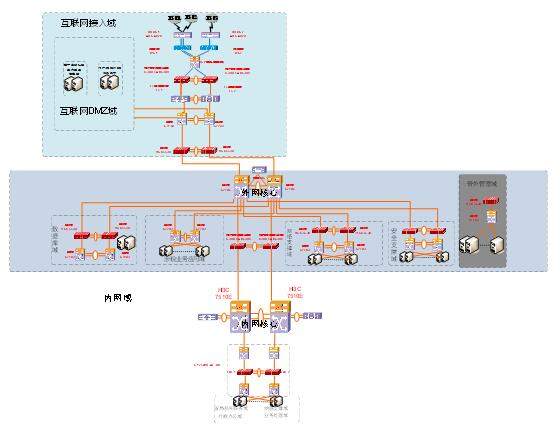
4个内网区域的服务器全部接入到2台内网S12508X-AF,并由内网S12508X-AF统一上行接入S7510E。
二、 组网拓扑

两台S12508X-AF使用IRF2技术虚拟成1台设备进行统一管理。服务器的网关配置在交换机上,通过路由引流到防火墙。防火墙给每个区域分配一个VFW,每个VFW上只有trust和untrust两个区域。两块防火墙板卡做IRF,虚拟成一台防火墙,IRF端口使用前面板的电口。防火墙会话同步和MAD检测使用防火墙的1个内联口,其他2个内联口用作数据传输。
防火墙处于三层模式,使用主备模式,规避跨框流量。主备模式需要防火墙内联口处于冗余组模式,故障时防火墙上下行三层地址全部切换。
三、 配置步骤
3.1S10500的内联口的配置如下
内联口允许的VLAN和FW上的聚合子接口终结的VLAN ID对应,通过VLAN的划分,将到不同Server的访问流量引到不同的自定义context中。
# Chassi1连接SecBladeIII,FW1的XGE1/0/1~XGE1/0/3组成聚合口BAG1:(略)
# 配置聚合口BAG1允许通过的VLAN:(略)
# Chassi2连接SecBlade III FW2的XGE1/0/1~XGE1/0/3组成聚合口BAG2:(略)
# 配置聚合口BAG2允许通过的VLAN:(略)
3.2防火墙板卡的接口及冗余组的配置步骤如下
1、配置聚合接口
创建聚合口RAG1和RAG2,将Slot 1和Slot 2的前3个内联口分别加入聚合口RAG1和RAG2。并创建RAG1的4个聚合子接口和RAG2的4个聚合子接口。(略)
2、配置冗余接口
创建4个冗余口Reth11~Reth14,分别将两个Slot的聚合子接口加入到一个冗余口。
如下举例4个冗余口,其中Reth11和Reth12口的成员口RAG1的子接口的优先级高,Reth 13和Reth 14口的成员口的RAG2的子接口的优先级高。
# 创建冗余口Reth11,成员接口为RAG1.1011和RAG2.1011,其中RAG1.1011的优先级为100,RAG2.1011的优先级为50。
[FW1] interface Reth 11
[FW1-Reth11] member interface Route-Aggregation1.1011 priority 100
[FW1-Reth11] member interface Route-Aggregation2.1011 priority 50
3、创建两个冗余组,每个冗余组分别控制2个冗余口。
# 配置Track,监测接口的状态。
[FW1] track 1 interface Route-Aggregation1
[FW1] track 2 interface Route-Aggregation 2
# 创建冗余组1,Node 1和Slot 1绑定,为主节点;Node 2和Slot2绑定,为备节点。
[FW1]redundancy group 1
[FW1-redundancy-group-1]preempt-delay 5
[FW1-redundancy-group-1] member interface Reth 11
[FW1-redundancy-group-1] member interface Reth 12
[FW1-redundancy-group-1]node 1
[FW1-redundancy-group-1-node-1]bind slot 1
[FW1-redundancy-group-1-node-1]priority 100
[FW1-redundancy-group-1-node-1] track 1 interface Route-Aggregation 1
[FW1-redundancy-group-1-node-1] quit
[FW1-redundancy-group-1]node 2
[FW1-redundancy-group-1-node-2]bind slot 2
[FW1-redundancy-group-1-node-2] priority 50
[FW1-redundancy-group-1-node-2] track 2 interface Route-Aggregation2
[FW1-redundancy-group-1-node-2]quit
[FW1-redundancy-group-1]quit
# 创建冗余组2,Node 1和Slot 1绑定,为备节点;Node 2和Slot2绑定,为主节点。(略)
4、创建2个context,分别将4个冗余口两两共享加入到这2个context中。
# 创建自定义context 1,将冗余口Reth11和Reth 12分配到该虚拟防火墙中。
[FW1]context 1
[FW1-context-2-1] allocate interface Reth11 to Reth12 share
[FW1-context-2-1]context start
# 创建自定义context 2,将冗余口Reth13和Reth 14分配到该虚拟防火墙中。
[FW1]context 2
[FW1-context-3-2]allocate interface Reth13 to Reth14 share
[FW1-context-3-2]context start
5、创建两个聚合子接口加入到一个冗余口,作为管理口。
#创建聚合子接口RAG1.1000,RAG2.1000。(略)
# 创建冗余口Reth1,成员接口为RAG1.1000和RAG2.1000。(略)
# 将该冗余口加入管理域。(略)
以context 1为例。进入自定义context 1,并设置系统名称为context1。
[FW1] context 1
[FW1-context-2-1]context start
[H3C]sysname context1
给冗余口配置IP地址,加入安全域并配置域间策略:(略)
#配置内网接口Reth11并加入trust域。
# 配置外部接口Reth12并加入untrust域。
#配置Untrust到Trust的域间策略,允许用户访问内部服务器。
#配置OSPF并配置相应的域间策略。(略)
# 配置Untrust和Local之间的域间策略,允许OSPF报文到达本地和从本地发出。(略)
# 创建对象组。
[context1]object-group ip address external
[context1-obj-grp-ip-external]network subnet 222.173.1.0 255.255.255.240
# 创建域间策略对象。
[context1]object-policy ip Untrust-Local
[context1-object-policy-ip-Untrust-Local]rule 0 pass source-ip external service ospf counting
[context1]object-policy ip local-untrust
[context1-object-policy-ip-Local-Untrust]rule 0 pass service ospf counting
#创建域间策略,并引用域间策略对象。
[context1]zone-pair security source untrust destination local
[context1-zone-pair-security-Untrust-Local]object-policy apply ip Untrust-Local
[context1]zone-pair security source local destination untrust
[context1-zone-pair-security-Local-Untrust]object-policy apply ip Local-Untrust
7、开启会话备份
[context1]session synchronization enable
[context1]session synchronization dns
[context1]session synchronization http
备注:http、dns的会话备份可以根据需要选择性配置。
2017年05月
本期文章
-
卷首语
-
公司动态
-
行业聚焦
-
产品推荐
-
案例介绍
-
经验共享
-
培训天地

 您的位置:
您的位置: